
Scraping process, which removes the remaining bits of bark and green growth from the bast and softens and spreads the fibers. To insure proper scraping, three different clam shells are used. Each shell has a different degree of courseness. The three types of clam shells are pipi, pae, and 'asi.
Sunday, January 31, 2010
Scraping process
Calculates rpm milling machine
 n = ( Vc x 1000 ) / (phi x d )
Description :
- Vc = Velocity cutting
- 1000 = Coeficient factor
- phi = Constanta
- d = Cutter diameter
Saturday, January 30, 2010
Calculates rpm turning machine

n = ( Vc x 1000 ) / (phi x d )
description :
Vc = Velocity cutting
1000 = Coeficient factor
phi = Constanta
d = Workpiece diameter
Turning process
 Turning is a form of machining, a material removal process, which is used to create rotational parts by cutting away unwanted material. The turning process requires a turning machine or lathe, workpiece, fixture, and cutting tool. The workpiece is a piece of pre-shaped material that is secured to the fixture, which itself is attached to the turning machine, and allowed to rotate at high speeds. The cutter is typically a single-point cutting tool that is also secured in the machine, although some operations make use of multi-point tools. The cutting tool feeds into the rotating workpiece and cuts away material in the form of small chips to create the desired shape. Turning is used to produce rotational, typically axi-symmetric, parts that have many features, such as holes, grooves, threads, tapers, various diameter steps, and even contoured surfaces. Parts that are fabricated completely through turning often include components that are used in limited quantities, perhaps for prototypes, such as custom designed shafts and fasteners. Turning is also commonly used as a secondary process to add or refine features on parts that were manufactured using a different process. Due to the high tolerances and surface finishes that turning can offer, it is ideal for adding precision rotational features to a part whose basic shape has already been formed.
Cylindrical grinding process
 The cylindrical grinder is a type of grinding machine used to shape the outside of an object. The cylindrical grinder can work on a variety of shapes however, the object must have a central axis of rotation. This includes but is not limited to such shapes as a cylinder, an ellipse, a cam, or a crankshaft.
Cylindrical Grinding is defined as having four essential actions
- The work (object) must be constantly rotating
- The grinding wheel must be constantly rotating
- The grinding wheel is fed towards and away from the work
- Either the work or the grinding wheel is traversed with the respect to the other.
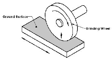
Surface grinding process
 Surface Grinding is a manufacturing process which moves or grinding wheel relative a surface in a plane while a grinding wheel contacts the surface and removes a minute amount of material, such that a flat surface is created. The term “surface grinding” designates any process which accurately processes or grinds a surface.
Surface grinding methods include: horizontal-spindle, vertical-spindle, vertical-spindle rotary grinding, horizontal spindle single disk, and vertical swivel head grinding.
Parts may require surface grinding for several reasons. The following are a few of the more common reasons:
- Produce a very flat surface.
- Very accurate thickness tolerance specified.
- A very smooth surface roughness Ra is specified/required.
- Cutting tool sharpening
Surface grinding machines and processes where first developed to to manufacture very tight tight tolerances, smooth surface finishes, and removing material from very hard materials .
 Horizontal-spindle reciprocating table surface grinding | |||
 Vertical-spindle rotary table surface grinding | |||
| |||


How to use micrometer

Place the object whose length, diameter, or thickness is to be measured between the micrometer's measuring rods.
-
Turn the barrel or friction screw to close the rods around the object to be measured. The rods should lightly touch the object between them but not clamp down on it.
-
Flip the locking lever to lock the measuring rods in place.
-
Read the value just exposed by the thimble on the central line of the cylinder. This value is in millimeters. Typically, there is a mark every half-millimeter, with the millimeter marks rising above the central line and the half-millimeter marks going below it.
-
Read the mark on the thimble aligned with the central line on the cylinder. This mark is in hundredths of millimeters. There are 50 such marks, meaning that each turn of the thimble corresponds to half a millimeter, the distance between the upward and downward marks on the cylinder central line.
- Step 6
Add these values together. This is the measurement of the object between the measuring rods.
Wednesday, January 6, 2010
How to use caliper

Firstly, the workpiece nipped with part of jaw under then the workpiece calculated with correctness differs in according to slide calipers correctness.
Kinds of Measuring Instrument
1. Ruler


A ruler, or rule, is an instrument used geometri, technical drawing and engineering/building to measure distances and/or to rule straight lines. Strictly speaking, the ruler is essentially a straightedge used to rule lines and the calibrated instrument used for determining measurement is called a "measure". However, common usage implies that a ruler is a straightedge that is calibrated for making measurements.
2. Cali per
per
A caliper is a device used to measure the distance between two symmetrically opposing sides. A caliper can be as simple as a compass with inward or outward-facing points. The tips of the caliper are adjusted to fit across the points to be measured, the caliper is then removed and the distance read by measuring between the tipswith a measuring tool, such as a ruler.
3. Mic rometer
A micrometer sometimes known as a micrometer screw gauge, is a device used widely in mechanical engineering and machining as well as most mechanical trades for precision measurement, along with other metrological instruments such as dial caliper and vernier caliper. Micrometers are often, but not always, in the form of calipers.
4. Tape mea sure
sure
A tape measure or measuring tape is a flexible form of ruler. It consists of a ribbon of cloth, plastic, fiber glass, or metal strip with linear-measurement markings. It is a common measuring tool. Its flexibility allows for a measure of great length to be easily carried in pocket or toolkit and permits one to measure around curves or corners.
Measurement and Inspection
Metrologi geometric is measurement of geometry an measure object covering dimension
( measure), form, position and surface roughness.
There is a four way of measurement, such as :
1. External of measurement
2. Internal of measure ment
3. Step of measurement
4. Depth of measurement
Subscribe to:
Posts (Atom)

